F51 Duplex Steel Blind Flanges
Home » ASTM A182 Duplex Steel F51 Blind Flange

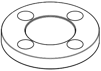
ASTM A182 DSS F51 Blind Flange
UNS S31803, 1.4462, ASTM A182 F51 Blind Flange
Duplex Steel F51 BLRF Flange
UNS S31803, 1.4462, ASTM A182 F51 BLRF Flange
ASTM A182 DSS F51 Blind Flange
UNS S32205, 1.4462, ASTM A182 F51 Blind Flange
Duplex Steel F51 Raised Face Blind Flange
UNS S32205, 1.4462, ASTM A182 F51 Blind Raised Face Flange
Duplex Steel F51 Blind Flanges are commonly used in various industrial applications due to their excellent mechanical strength, weldability, and impressive general, pitting, stress, and crevice corrosion resistance. These flanges made from ASTM A182 F51 duplex stainless steel have a chemical composition of carbon, chromium, manganese, molybdenum, nitrogen, nickel, and phosphorus.
The F51 Blind Flange is the most commonly used coil material for repairing vaporizers. Its composition of 18% chromium, 8% nickel, and just 0.08% carbon makes it resistant to corrosion, dimensionally accurate, and durable. With a maximum Brinell hardness of 290HB and a 25% elongation rate, this Blind Flange grade F51 is an excellent choice for various industrial applications.
These F51 Blind Flanges are ideal for high-pressure and high-temperature applications such as boilers, condensers, heat exchangers, power plants, and petroleum industry applications.
At Hex Forge Inc, we are a trusted manufacturer and supplier of high-quality F51 Blind Flanges, including F51 Duplex Steel Spectacle Blind Flanges. If you require specific dimensions for your F51 Blind Flange, our A182 F51 Duplex Steel Blind Flange Dimensions chart provides detailed information on size and weight.
F51 Duplex Steel Spectacle Blind Flange, DUPLEX STEEL S32205 BLIND FLANGE, ASTM A182 DSS F51 BLIND FLANGE, ASTM A182 DUPLEX STEEL F51 BLIND FLANGE MANUFACTURER.
Table of Content
- About Duplex Steel F51 Blind Flanges
- Standard Specification Of ASTM A182 F51 Flange
- Equivalent Grade Of ASTM A182 F51 Blind Flange
- Duplex Steel F51 Flange Pressure Rate
- A182 F51 Duplex Steel Blind Flange Dimensions Class 150
- ASTM A182 Duplex Steel Flanges Size Chart
- ASTM A182 Duplex Steel Flanges Weight Chart
- ASTM A182 Gr F51 Chemical Composition
- Mechanical Properties Of ASTM A182 F51 Blind Flange
- Ready Stock Of Duplex Steel F51 Blind Flanges
- People also Search for F51 DSS Blind Flange
- We Export Duplex Steel F51 Blind Flanges Across the Globe
ASTM A182 DUPLEX STEEL F51 BLIND FLANGE SUPPLIER, F51 DUPLEX STEEL RAISED FACE BLIND FLANGES, UNS S31803 BLIND FLANGE Manufacturer and Supplier in Mumbai, India.
We offer F51 Blind Flanges in various dimensions, including those specified in the ASTM A182 DSS Blind Flange Chart. These charts provide valuable information on the size and weight of the flanges, making it easier for customers to select the appropriate product for their specific requirements. Additionally, we offer F51 Duplex Steel Spectacle Blind Flanges that are ideal for applications requiring a temporary or permanent blind in a piping system.
Choose Hex Forge Inc for your F51 Blind Flange needs, and we guarantee that you will receive high-quality products that meet your requirements.
What is the full form of BLRF FLANGES?
BLRF stands for Blind Raised Face flanges. BLRF flanges are used in the piping industry to cap off the end of a pipe or valve or to connect two pipes. They are circular and have a raised face, which helps to create a tight seal between the flange and the gasket. The raised face also provides additional strength to the flange, making it suitable for high-pressure applications. BLRF flanges are typically made from carbon steel, stainless steel, or alloy steel, depending on the application’s specific requirements. They are available in various sizes and pressure ratings and are commonly helpful in industries such as oil and gas, chemical processing, and power generation.
How to use a F51 Duplex Steel spectacle blind flange?
F51 Duplex Steel Spectacle Blind flanges block off a section of a pipeline, typically during maintenance or when a pipe needs to be taken out of service. To use the flange, it is first necessary to determine the application’s correct size and pressure rating. Once the appropriate flange has been selected, it should be installed between two pipe flanges, with the gasket in place and the bolts tightened to the proper torque. The spectacle blind section of the flange can then be removed to allow access to the pipe. It is crucial to ensure that the remaining flange faces are clean and free of debris to ensure a tight seal. The spectacle blind flange should be replaced after the work is completed to restore the pipeline to the entire operation. Regular inspections should ensure the flange is secure and functioning correctly.
Standard Specification Of ASTM A182 F51 Flange
Specification : ASTM A182 / ASME SA182
Standard : ANSI/ASME B16.5, B16.47 Series A & B, B16.48, BS4504, BS 10, EN-1092, DIN, ANSI Flanges, ASME Flanges, BS Flanges, DIN Flanges, EN Flanges, GOST Flange, ASME/ANSI B16.5/16.36/16.47A/16.47B, MSS SP44, ISO70051, JISB2220, BS1560-3.1, API7S-15, API7S-43, API605, EN1092
Size : 1/2″ (15 NB) to 48″ (1200NB) DN10~DN5000
Class : 150 LBS, 300 LBS, 600 LBS, 900 LBS, 1500 LBS, 2500 LBS, DIN Standard ND-6,10, 16, 25, 40 Etc.
Connect Type/ Flange Face Type : Raised Face (RF), Ring Type Joint (RTJ), Flat Face (FF), Large Male-Female (LMF), Small Male-Female (SMF)
JIS : JIS B2220, JIS B2221, 5K, 10K, 16K, 20K, 30K, 40K, 63K
DIN : DIN 2527, DIN 2566, DIN 2573, DIN 2576, DIN 2641, DIN 2642, DIN 2655, DIN 2656, DIN 2627, DIN 2628, DIN 2629, DIN 2631, DIN 2632, DIN 2633, DIN 2634, DIN 2635, DIN 2636, DIN 2637, DIN 2638, DIN 2673
BS : BS 4504, BS 4504, BS 1560, BS 10

Equivalent Grade Of ASTM A182 F51 Blind Flange
| STANDARD | UNS | WERKSTOFF NR. |
| Duplex 2205 | S31803 | 1.4462 |
WE MANUFACTURE ASTM A182 STAINLESS STEEL 304 BLIND FLANGE AS PER INTERNATIONAL STANDARDS & SPECIFICATIONS. 304L SS BLRF FLANGE MANUFACTURERS IN INDIA, CUSTOM SIZES SS 304/304L BLIND FLANGE CAN BE PRODUCED AS PER CLIENT DRAWING.
Dimensional Standards
- American Standard (ANSI/ASME/AWWA)
- German Standard (DIN)
- European Standard (EN)
- Japanese Standard (JIS)
- British Standard (BS)
- MSS Standard (MSS-SP)
- Petroleum Standard (API)
- Russian Standard (GOST)
- South African Standard (SABS / SANS)
Manufacturing Facilities :
- Raw material cutting: band saw
- Cold Forging
- Open / Close Die Forging & Rolling: Hammer / Press / Ring Rolling
- Machining: CNC lathes/SPM lathes
- Bolt Hole drilling: High speed CNC Vertical Machining Center
- Heat treatment: Solution Annealing (batch annealing furnaces)
- Seamless Rolled Ring Forging
Duplex Steel F51 Flange Pressure Rate
| ASME B16.5 Pressure Ratings | |||||||
|---|---|---|---|---|---|---|---|
| Temperature (°C) | Class | ||||||
| Class 150 | Class 300 | Class 400 | Class 600 | Class 900 | Class 1500 | Class 2500 | |
| -29 – 38 | 19.8 | 51.7 | 68.9 | 103.4 | 155 | 259 | 431 |
| 50 | 19.5 | 51.7 | 68.9 | 103.4 | 155 | 259 | 431 |
| 100 | 17.7 | 51.5 | 68.7 | 103.0 | 155 | 258 | 429 |
| 150 | 15.8 | 50.2 | 66.8 | 100.3 | 151 | 251 | 418 |
| 200 | 13.8 | 48.6 | 64.8 | 97.2 | 146 | 243 | 405 |
| 250 | 12.1 | 46.3 | 61.7 | 92.7 | 139 | 232 | 386 |
| 300 | 10.2 | 42.9 | 57.0 | 85.7 | 129 | 214 | 357 |
| 325 | 9.3 | 41.4 | 55.0 | 82.6 | 124 | 207 | 344 |
| 350 | 8.4 | 40.0 | 53.4 | 80.0 | 120 | 200 | 334 |
| 375 | 7.4 | 37.8 | 50.4 | 75.7 | 114 | 189 | 315 |
| 400 | 6.5 | 34.7 | 46.3 | 69.4 | 104 | 174 | 290 |
| 425 | 5.5 | 28.8 | 38.4 | 57.5 | 86.3 | 144 | 240 |
| 450 | 4.6 | 23.0 | 30.7 | 46.0 | 69.0 | 115 | 192 |
| 475 | 3.7 | 17.1 | 22.8 | 34.2 | 51.3 | 85.4 | 142 |
| 500 | 2.8 | 11.6 | 15.4 | 23.2 | 34.7 | 57.9 | 96.5 |
| 538 | 1.4 | 5.9 | 7.9 | 11.8 | 17.7 | 29.5 | 49.2 |
A182 F51 Duplex Steel Blind Flange Dimensions Class 150
| ize in Inch | Size in mm | Outer Dia. | Flange Thick. | Hub OD | Flange Length | RF Dia. | RF Height | PCD | Socket Bore | No of Bolts | Bolt Size UNC | Machine Bolt Length | RF Stud Length | Hole Size | ISO Stud Size | Weight in kg |
|---|---|---|---|---|---|---|---|---|---|---|---|---|---|---|---|---|
| A | B | C | D | E | F | G | H | |||||||||
| 1/2 | 15 | 90 | 9.6 | 30 | 14 | 34.9 | 2 | 60.3 | 22.2 | 4 | 1/2 | 50 | 55 | 5/8 | M14 | 0.8 |
| 3/4 | 20 | 100 | 11.2 | 38 | 14 | 42.9 | 2 | 69.9 | 27.7 | 4 | 1/2 | 50 | 65 | 5/8 | M14 | 0.9 |
| 1 | 25 | 110 | 12.7 | 49 | 16 | 50.8 | 2 | 79.4 | 34.5 | 4 | 1/2 | 55 | 65 | 5/8 | M14 | 0.9 |
| 1 1/4 | 32 | 115 | 14.3 | 59 | 19 | 63.5 | 2 | 88.9 | 43.2 | 4 | 1/2 | 55 | 70 | 5/8 | M14 | 1.4 |
| 1 1/2 | 40 | 125 | 15.9 | 65 | 21 | 73 | 2 | 98.4 | 49.5 | 4 | 1/2 | 65 | 70 | 5/8 | M14 | 1.4 |
| 2 | 50 | 150 | 17.5 | 78 | 24 | 92.1 | 2 | 120.7 | 61.9 | 4 | 5/8 | 70 | 85 | 3/4 | M16 | 2.3 |
| 2 1/2 | 65 | 180 | 20.7 | 90 | 27 | 104.8 | 2 | 139.7 | 74.6 | 4 | 5/8 | 75 | 90 | 3/4 | M16 | 3.2 |
| 3 | 80 | 190 | 22.3 | 108 | 29 | 127 | 2 | 152.4 | 90.7 | 4 | 5/8 | 75 | 90 | 3/4 | M16 | 3.7 |
| 3 1/2 | 90 | 215 | 22.3 | 122 | 30 | 139.7 | 2 | 177.8 | 103.4 | 8 | 5/8 | 75 | 90 | 3/4 | M16 | 5 |
| 4 | 100 | 230 | 22.3 | 135 | 32 | 157.2 | 2 | 190.5 | 116.1 | 8 | 5/8 | 75 | 90 | 3/4 | M16 | 5.9 |
| 5 | 125 | 255 | 22.3 | 164 | 35 | 185.7 | 2 | 215.9 | 143.8 | 8 | 3/4 | 85 | 95 | 7/8 | M20 | 6.8 |
| 6 | 150 | 280 | 23.9 | 192 | 38 | 215.9 | 2 | 241.3 | 170.7 | 8 | 3/4 | 85 | 100 | 7/8 | M20 | 8.6 |
| 8 | 200 | 345 | 27 | 246 | 43 | 269.9 | 2 | 298.5 | 221.5 | 8 | 3/4 | 90 | 110 | 7/8 | M20 | 13.7 |
| 10 | 250 | 405 | 28.6 | 305 | 48 | 323.8 | 2 | 362 | 276.2 | 12 | 7/8 | 100 | 115 | 1 | M24 | 19.5 |
| 12 | 300 | 485 | 30.2 | 365 | 54 | 381 | 2 | 431.8 | 327 | 12 | 7/8 | 100 | 120 | 1 | M24 | 29 |
| 14 | 350 | 535 | 33.4 | 400 | 56 | 412.8 | 2 | 476.3 | 359.2 | 12 | 1 | 115 | 135 | 1 1/8 | M27 | 41 |
| 16 | 400 | 595 | 35 | 457 | 62 | 469.9 | 2 | 539.8 | 410.5 | 16 | 1 | 115 | 135 | 1 1/8 | M27 | 54 |
| 18 | 450 | 635 | 38.1 | 505 | 67 | 533.4 | 2 | 577.9 | 461.8 | 16 | 1 1/8 | 125 | 145 | 1 1/4 | M30 | 59 |
| 20 | 500 | 700 | 41.3 | 559 | 71 | 584.2 | 2 | 635 | 513.1 | 20 | 1 1/8 | 140 | 160 | 1 1/4 | M30 | 75 |
| 24 | 600 | 815 | 46.1 | 663 | 81 | 692.2 | 2 | 749.3 | 616 | 20 | 1 1/4 | 150 | 170 | 1 3/8 | M33 | 100 |
ASTM A182 DSS Blind Flange Chart
| DN In inches | Dimension | ASME B16.5 Dimensional Sizes 1/2 inches to 2 1/2 inches | ||||||||||||||
|---|---|---|---|---|---|---|---|---|---|---|---|---|---|---|---|---|
| 125 LBS 150 LBS | 300 LBS | 400 LBS | 600 LBS | 900 LBS | 1500 LBS | 2500 LBS | ||||||||||
| inches | millimeter | inches | millimeter | inches | millimeter | inches | millimeter | inches | millimeter | inches | millimeter | inches | millimeter | |||
| 1/2 | A | 3 1/2 | 88.9 | 3 3/4 | 95.2 | 3 3/4 | 95.2 | 3 3/4 | 95.2 | 4 3/4 | 121 | 4 3/4 | 121 | 5 1/4 | 133.4 | |
| b | 7/16 | 11.1 | 9/16 | 14.3 | 9/16 | 14.3 | 9/16 | 14.3 | 7/8 | 22.2 | 7/8 | 22.2 | 1 3/16 | 30.2 | ||
| D2 | 1 3/8 | 34.9 | 1 3/8 | 34.9 | 1 3/8 | 34.9 | 1 3/8 | 34.9 | 1 3/8 | 34.9 | 1 3/8 | 34.9 | 1 3/8 | 34.9 | ||
| D1 | 2 3/8 | 60.3 | 2 5/8 | 66.7 | 2 5/8 | 66.7 | 2 5/8 | 66.7 | 3 1/4 | 82.6 | 3 1/4 | 82.6 | 3 1/2 | 88.9 | ||
| n | 4 | 4 | 4 | 4 | 4 | 4 | 4 | 4 | 4 | 4 | 4 | – | 4 | 44 | ||
| d | 5/8 | 15.9 | 5/8 | 15.9 | 5/8 | 15.9 | 5/8 | 15.9 | 7/8 | 22.2 | 7/8 | 22.2 | 7/8 | 22.2 | ||
| 3/4 | A | 3 7/8 | 98.4 | 4 5/8 | 117.5 | 4 5/8 | 117.5 | 4 5/8 | 117.5 | 5 1/8 | 130 | 5 1/8 | 130 | 5 1/2 | 139.7 | |
| b | 1/2 | 12.7 | 5/8 | 15.9 | 5/8 | 15.9 | 5/8 | 15.9 | 1 | 25.4 | 1 | 25.4 | 1 1/4 | 31.8 | ||
| D2 | 1 11/16 | 42.9 | 1 11/16 | 42.9 | 1 11/16 | 42.9 | 1 11/16 | 42.9 | 1 11/16 | 42.9 | 1 11/16 | 42.9 | 1 11/16 | 42.9 | ||
| D1 | 2 3/4 | 69.8 | 3 1/4 | 82.5 | 3 1/4 | 82.5 | 3 1/4 | 82.5 | 3 1/2 | 88.9 | 3 1/2 | 88.9 | 3 3/4 | 95.2 | ||
| n | 4 | 4 | 4 | 4 | 4 | 4 | 4 | 4 | 4 | 4 | 4 | – | 4 | 44 | ||
| d | 5/8 | 15.9 | 3/4 | 19 | 3/4 | 19 | 3/4 | 19 | 7/8 | 22.2 | 7/8 | 22.2 | 7/8 | 22.2 | ||
| 1 | A | 4 1/4 | 108 | 4 7/8 | 123.8 | 4 7/8 | 123.8 | 4 7/8 | 123.8 | 5 7/8 | 149.2 | 5 7/8 | 149.2 | 6 1/4 | 159 | |
| b | 9/16 | 14.3 | 11/16 | 17.5 | 11/16 | 17.5 | 11/16 | 17.5 | 1 1/8 | 28.6 | 1 1/8 | 28.6 | 1 3/8 | 34.9 | ||
| D2 | 2 | 50.8 | 2 | 50.8 | 2 | 50.8 | 2 | 50.8 | 2 | 50.8 | 2 | 50.8 | 2 | 50.8 | ||
| D1 | 3 1/8 | 79.4 | 3 1/2 | 88.9 | 3 1/2 | 88.9 | 3 1/2 | 88.9 | 4 | 102 | 4 | 102 | 4 1/4 | 108 | ||
| n | 4 | 4 | 4 | 4 | 4 | 4 | 4 | 4 | 4 | 4 | 4 | 4 | 4 | 4 | ||
| d | 5/8 | 15.9 | 3/4 | 19 | 3/4 | 19 | 3/4 | 19 | 1 | 25.4 | 1 | 25.4 | 1 | 25.4 | ||
| 1 1/4 | A | 4 5/8 | 117.5 | 5 1/4 | 133.4 | 5 1/4 | 133.4 | 5 1/4 | 133.4 | 6 1/4 | 159 | 6 1/4 | 159 | 7 1/4 | 184.2 | |
| b | 5/8 | 15.9 | 3/4 | 19 | 13/16 | 20.6 | 13/16 | 20.6 | 1 1/8 | 28.6 | 1 1/8 | 28.6 | 1 1/2 | 38.1 | ||
| D2 | 2 1/2 | 63.5 | 2 1/2 | 63.5 | 2 1/2 | 63.5 | 2 1/2 | 63.5 | 2 1/2 | 63.5 | 2 1/2 | 63.5 | 2 1/2 | 63.5 | ||
| D1 | 3 1/2 | 88.9 | 3 7/8 | 98.4 | 3 7/8 | 98.4 | 3 7/8 | 98.4 | 4 3/8 | 111 | 4 3/8 | 111 | 5 1/8 | 130 | ||
| n | 4 | 4 | 4 | 4 | 4 | 4 | 4 | 4 | 4 | 4 | 4 | 4 | 4 | 4 | ||
| d | 5/8 | 15.9 | 3/4 | 19 | 3/4 | 19 | 3/4 | 19 | 1 | 25.4 | 1 | 25.4 | 1 1/8 | 28.6 | ||
| 1 1/2 | A | 5 | 127 | 6 1/8 | 155.6 | 6 1/8 | 155.6 | 6 1/8 | 155.6 | 7 | 177.8 | 7 | 177.8 | 8 | 203 | |
| b | 11/16 | 17.5 | 13/16 | 20.6 | 7/8 | 22.2 | 7/8 | 22.2 | 1 1/4 | 31.8 | 1 1/4 | 31.8 | 1 3/4 | 44.5 | ||
| D2 | 2 7/8 | 73 98 | 2 7/8 | 73 | 2 7/8 | 73 | 2 7/8 | 73 | 2 7/8 | 73 | 2 7/8 | 73 | 2 7/8 | 73 | ||
| D1 | 3 7/8 | 4 | 4 1/2 | 114 | 4 1/2 | 114 | 4 1/2 | 114 | 4 7/8 | 124 | 4 7/8 | 124 | 5 3/4 | 146 | ||
| n | 4 | 4 | 4 | 4 | 4 | 4 | 4 | 4 | 4 | 4 | 4 | 4 | 4 | 4 | ||
| d | 5/8 | . 15.9 | 7/8 | 22.2 | 7/8 | 22.2 | 7/8 | 22.2 | 1 1/8 | 28.6 | 1 1/8 | 28.6 | 1 1/4 | 31.8 | ||
| 2 | A | 6 | 152.4 | 6 1/2 | 165.1 | 6 1/2 | 165.1 | 6 1/2 | 165.1 | 8 1/2 | 215.9 | 8 1/2 | 215.9 | 9 1/4 | 234.9 | |
| b | 3/4 | 19 | 7/8 | 22.2 | 1 | 25.4 | 1 | 25.4 | 1 1/2 | 38.1 | 1 1/2 | 38.1 | 2 | 50.8 | ||
| D2 | 3 5/8 | 92.1 | 3 5/8 | 92.1 | 3 5/8 | 92.1 | 3 5/8 | 92.1 | 3 5/8 | 92.1 | 3 5/8 | 92.1 | 3 5/8 | 92.1 | ||
| D1 | 4 3/4 | 121 | 5 | 127 | 5 | 127 | 5 | 127 | 6 1/2 | 165.1 | 6 1/2 | 165.1 | 6 3/4 | 171 | ||
| n | 4 | 4 | 8 | 8 | 8 | 8 | 8 | 8 | 8 | 8 | 8 | 8 | 8 | 8 | ||
| d | 3/4 | 19 | 3/4 | 19 | 3/4 | 19 | 3/4 | 19 | 1 | 25.4 | 1 | 25.4 | 1 1/8 | 28.6 | ||
| 2 1/2 | A | 7 | 177.8 | 7 1/2 | 190.5 | 7 1/2 | 190.5 | 7 1/2 | 190.5 | 9 5/8 | 244 | 9 5/8 | 244 | 10 1/2 | 266.7 | |
| b | 7/8 | 22.2 | 1 | 25.4 | 1 1/8 | 28.6 | 1 1/8 | 28.6 | 1 5/8 | 41.3 | 1 5/8 | 41.3 | 2 1/4 | 57.2 | ||
| D2 | 4 1/8 | 104.8 | 4 1/8 | 104.8 | 4 1/8 | 104.8 | 4 1/8 | 104.8 | 4 1/8 | 105 | 4 1/8 | 105 | 4 1/8 | 105 | ||
| D1 | 5 1/2 | 139.7 | 5 7/8 | 149.2 | 5 7/8 | 149.2 | 5 7/8 | 149.2 | 7 1/2 | 190.5 | 7 1/2 | 190.5 | 7 3/4 | 197 | ||
| n | 4 | 4 | 8 | 8 | 8 | 8 | 8 | 8 | 8 | 8 | 8 | 8 | 8 | 8 | ||
| d | 3/4 | 19 | 7/8 | 22.2 | 7/8 | 22.2 | 7/8 | 22.2 | 1 1/8 | 28.6 | 1 1/8 | 28.6 | 1 1/4 | 31.8 | ||
ASTM A182 Duplex Steel Flanges Weight Chart
| Flange Weights by Pressure Class and Size | ||||||||||||||||||
|---|---|---|---|---|---|---|---|---|---|---|---|---|---|---|---|---|---|---|
| Pipe Size | 150 # | 300 # | 600 # | 900 # | 1500 # | 2500 # | ||||||||||||
| WN | SO | BLD | WN | SO | BLD | WN | SO | BLD | WN | SO | BLD | WN | SO | BLD | WN | SO | BLD | |
| 1/2″ | 2 | 1 | 1 | 2 | 1 | 1 | 2 | 2 | 2 | SEE 1500 # WEIGHTS | 5 | 4 | 4 | 7 | 7 | 7 | ||
| 3/4″ | 2 | 2 | 2 | 3 | 3 | 3 | 4 | 3 | 3 | SEE 1500 # WEIGHTS | 6 | 5 | 6 | 8 | 8 | 8 | ||
| 1″ | 3 | 2 | 2 | 4 | 3 | 3 | 4 | 4 | 4 | SEE 1500 # WEIGHTS | 9 | 8 | 8 | 12 | 11 | 11 | ||
| 1 1/2″ | 4 | 3 | 3 | 7 | 6 | 6 | 8 | 7 | 8 | SEE 1500 # WEIGHTS | 13 | 12 | 13 | 25 | 22 | 23 | ||
| 2″ | 6 | 5 | 5 | 9 | 7 | 8 | 12 | 9 | 10 | SEE 1500 # WEIGHTS | 25 | 25 | 25 | 42 | 37 | 39 | ||
| 2 1/2″ | 8 | 7 | 7 | 12 | 10 | 12 | 18 | 13 | 15 | SEE 1500 # WEIGHTS | 36 | 36 | 35 | 52 | 55 | 56 | ||
| 3″ | 10 | 8 | 9 | 15 | 13 | 16 | 23 | 16 | 20 | 31 | 26 | 29 | 48 | 48 | 48 | 94 | 83 | 86 |
| 4″ | 15 | 13 | 17 | 25 | 22 | 27 | 42 | 37 | 41 | 53 | 53 | 54 | 73 | 73 | 73 | 145 | 125 | 130 |
| 5″ | 19 | 15 | 20 | 32 | 28 | 35 | 68 | 63 | 68 | 86 | 83 | 87 | 130 | 130 | 140 | 245 | 210 | 225 |
| 6″ | 24 | 19 | 26 | 42 | 39 | 50 | 81 | 80 | 86 | 110 | 110 | 115 | 165 | 165 | 160 | 380 | 325 | 345 |
| 8″ | 39 | 30 | 45 | 67 | 58 | 81 | 120 | 115 | 140 | 175 | 170 | 200 | 275 | 260 | 300 | 580 | 485 | 530 |
| 10″ | 52 | 43 | 70 | 91 | 81 | 124 | 190 | 170 | 230 | 260 | 245 | 290 | 455 | 435 | 510 | 1075 | 930 | 1025 |
| 12″ | 80 | 64 | 110 | 140 | 115 | 185 | 225 | 200 | 295 | 325 | 325 | 415 | 690 | 580 | 690 | 1525 | 1100 | 1300 |
| 14″ | 110 | 90 | 140 | 180 | 165 | 250 | 280 | 230 | 355 | 400 | 400 | 520 | 940 | NA | 975 | NA | NA | NA |
| 16″ | 140 | 98 | 180 | 250 | 190 | 295 | 390 | 330 | 495 | 495 | 425 | 600 | 1250 | NA | 1300 | NA | NA | NA |
| 18″ | 150 | 130 | 220 | 320 | 250 | 395 | 475 | 400 | 630 | 680 | 600 | 850 | 1625 | NA | 1750 | NA | NA | NA |
| 20″ | 180 | 165 | 285 | 400 | 315 | 505 | 590 | 510 | 810 | 830 | 730 | 1075 | 2050 | NA | 2225 | NA | NA | NA |
| 22″ | 225 | 185 | 355 | 465 | 370 | 640 | 720 | 590 | 1000 | NA | NA | NA | NA | NA | NA | NA | NA | NA |
| 24″ | 260 | 220 | 430 | 580 | 475 | 790 | 830 | 730 | 1250 | 1500 | 1400 | 2025 | 3325 | NA | 3625 | NA | NA | NA |
ASTM A182 Gr F51 Chemical Composition
| Grade | C | Mn | Si | P | S | Cr | Mo | Ni | N | Fe |
| S31803 | 0.030 max | 2.00 max | 1.00 max | 0.030 max | 0.020 max | 22.0 – 23.0 | 3.0 – 3.5 | 4.50 – 6.50 | 0.14 – 0.20 | 63.72 min |
Mechanical Properties Of ASTM A182 F51 Blind Flange
| Grade | Density | Melting Point | Tensile Strength | Yield Strength (0.2%Offset) | Elongation |
| S31803 | 7.8 g/cm3 | 1350 °C (2460 °F) | Psi – 116000 , MPa – 800 | Psi – 80000 , MPa – 550 | 15 % |
We are One Of The Most Trusted Supplier Of F51 Duplex Steel Blind Flange in India. For final ASTM A182 DSS F51 Blind Flange Price List
Please Call on +91 96194 44982 or drop an E-Mail : [email protected]
Ready Stock Of Duplex Steel F51 Blind Flanges
- DSS F51 Blind Pipe Flange Stock At Best Price
- Duplex F51 Table E Blind Flange
- F51 Duplex Steel Blind Pipe Flange 1500#
- F51 Duplex Stainless Steel BS Blind Flange
- Duplex Steel 1.4462 Blind Flange
- F51 DSS MDSS SP 44 Blind Flange Manufacturer
- ASTM A182 F51 DSS Blind Flange dimensions 900#
- DSS F51 DIN Blind Flange Stockist
- DSS F51 AWWA C207 Class B Blind Flange
- DSS 1.4462 Blind Flange Class 600
- Duplex Steel F51 Industrial Blind Flanges
- UNS S32205 Blind Flange in India
- F51 Duplex Steel ASME B16.5 Blind Flange
- DSS S31803 Blind Flanges
- ASTM A182 DSS F51 JIS B2220 Blind Pipe Flange
- ASTM A182 Duplex Steel F51 BLRTJ Flange
- Duplex Steel F51 Industrial Blind Flange
- DSS 2205 BS 4504 Blind Flanges
- DSS F51 ASME B16.47 Blind Flange
- DSS F51 JIS Standard Blind Raised Face Flange
- Duplex Steel 1.4462 BLFF Flange
- ASTM A182 DSS F51 EN 1092-2 PN16 Blind Flange
- DSS F51 Blind Flange ASME B16.5 Class 300
- Duplex Steel F51 Raised Face Blind Flange
- F51 Duplex Stainless Steel Blind Pipe Flange
- Duplex Steel F51 RFBL Flange Manufacturer
- F51 Duplex AWWA C207 Class E Blind Flange
- ASTM A182 FF51 BS 10 Table E Blind Flange
People also Search for F51 DSS Blind Flange
f51 duplex steel blind flange price list, f51 duplex steel blind flange weight chart, buy duplex steel f51 blrtj flanges asme b16.5 class 150, cheap price duplex steel f51 table e blind flange, astm a182 dss ff51 blind flange manufacturer, dss f51 b16.47 series a (mss sp44) blind flange 900lb, dss f51 blind flange b16.47 series a manufacturers in mumbai.
We Export Duplex Steel F51 Blind Flanges Across the Globe
MIDDLE EAST
| AFRICA
| EUROPE
| ASIA
|
Domestic Supply DSS F51 Blind Flanges
| Bengaluru | Mumbai | Chennai | Hyderabad | Kolkata | Pune |
| New Delhi | Ahmedabad | Jaipur | Surat | Salem | Gandhinagar |
| Bhiwandi | Tiruppur | Sivakasi | Jamnagar | Thiruvananthapuram | Rajahmundry |
| Bhubaneswar | Vijaywada | Firozabad | Bokaro Steel City | Rajkot | Bharuch |
| Panna | Raipur | Cochin | Ludhiana | Panipat | Durgapur |
| Peenya | Pimpri-Chinchwad | Channapatna | Kharagpur | Nashik | Bareilly |
| Varanasi | Haldia | Rourkela | Bangalore | Moradabad | Indore |
| Visakhapatnam | Trivandrum | Pithampur | Dibrugarh | Angul | Gwalior |
| Coimbatore | Kannur | Nagpur | Vadodara | Rudrapur | Noida |
| Agra | Bhagalpur | Jamshedpur | Bhilai | Lucknow | kanpur |
| Thane | Bhopal | Navi Mumbai | Vasai | Bikaner | Maharashtra |
Products
- Stainless Steel
- Duplex Steel
- Duplex Steel Fasteners
- Duplex Steel Hex Bolt
- Duplex Steel Hex Nut
- Duplex Steel Stud Bolt
- Duplex Steel Washer
- Duplex Steel Flange
- Duplex Steel Blind Flange
- Duplex Steel Slip On Flange
- Duplex Steel WNRF Flange
- Duplex Steel Long Weld Neck Flange
- Duplex Steel Socket Weld Flange
- Duplex Steel Threaded Flange
- Duplex Steel Lap Joint Flange
- Duplex Steel RTJ Flange
- Duplex Steel Custom Drawing Flange
- Duplex Steel Tubes
- Super Duplex Steel
- Inconel
- Monel
- Hastelloy
- Titanium
- Cupro Nickel
- Copper
- Alloy 20
- Carbon Steel
- Aluminium Bronze
- Silicon Bronze
- Phosphorous Bronze
- Corten Steel
- Countries
- City
World wide Shipping

We Serve application Industry
Our products range of Duplex Steel F51 Blind Flange find application in various areas such as : Civil Construction Industries, Vessels, power Generation Units ( Nuclear, Ship Building Industries, Home Fittings, Heavy Engineering Industries, Pumps, Valves, Hydro or Thermal), Oil Expansion Projects, Fertilizer Plants, Off Shore & On Shore Oil Towers, Petro-Chemical Industries, Railways, Steel Plants etc, Civil Industries.
Hex Forge Inc. is a leading manufacturer, supplier, stockist, and exporter of fasteners, flanges and Tubes in a variety of types.
Address - 1: Pathan 4th Lane, DD road, Building 91, Plot 117 Mumbai 400004
Address - 2: Shall be added later
Company
Tech Info.
Quick Contact
Mail